Bent on Innovation
Posted February 22, 2021
Modern highway interchanges often require complex bridge geometry to safely divert traffic from one roadway to another.
This is especially true for interchanges where two limited access highways converge. These interchanges often have ramp configurations with higher travel speeds, resulting in flatter curves and braided geometry. Braided ramp geometry leads to the need for straddle bent caps where one ramp crosses over another roadway at a severe skew angle.
The I-91 Interchange 29 in Hartford, Conn., is an example of a high-speed highway interchange. The original interchange, built in 1990, connects Interstate 91 with Connecticut Route 5/15, which acts as a connector highway to Interstate 84 eastbound. The key feature in the interchange revolves around the connection between Interstate 91 northbound and Route 5/15 northbound. The interchange ramp is a steep, narrow single-lane with a traffic weave where the ramp meets Route 5/15. The proposed ramp is a two-lane high-speed ramp with greatly improved geometry and a flatter grade, and crosses Route 5/15 southbound at a severe skew in a braided configuration.
The design team investigated several ramp structure options, including tunnel-like configurations and long-span bridge options. Figure 1 depicts the crossing of these two roadways and the area in which vertical clearance was required between the two roadways. Cantilever post-tensioned concrete hammerhead bents were used in the final design, where there was ample vertical clearance for traffic to travel under the bent caps. A single straddle bent was used where the two roadways converge. The spans supported by the straddle bent cap are 215 ft on either side of the straddle bent.
The AASHTO LRFD Bridge Design Specifications contain provisions for the design of fracture-critical elements; however, many bridge owners shy away from fracture-critical designs. In 2012, the Federal Highway Administration (FHWA) issued a new Fracture Critical Policy. The policy included the designations of load path-redundant members (LPRMs), internally redundant members (IRMs), and system redundant members (SRMs) to address the design and asset management requirements for members like straddle bent caps.
|
The design of the Interchange ramp bridge straddle bent was based on providing load path redundancy. The concept was to design a cap with three I-girders bolted together with diaphragms, essentially providing a multi-girder bridge supporting another bridge. Figure 2 shows the details of the cross-section of the straddle bent. The concept for the design was multifaceted, with load path redundancy being the primary reason. The idea was that the fracture of one flange would not lead to the collapse of the entire straddle cap. The second reason was to facilitate shipping and erection. The straddle beam could be shipped and erected in one piece, two pieces, or even three pieces—providing flexibility to the contractor and erector. If a large crane was available on-site, it could be erected as one complete girder. If crane sizes were limited, the cap could be erected in three pieces.
|
Fig. 2. A typical cross section of the straddle bent. |
The spacing of the beams was set to provide ample access for future inspections and maintenance. The area between the beams is approximately 90 in. by 42 in. A small gap was detailed between the flanges to allow for airflow to keep the girders dry, and standard steel grating was placed on top of the bottom flanges to prevent maintenance tools from falling to the roadway below. Sealing plates were used on the top to prevent the ingress of water and snow, and access hole sizes and elevations were set to facilitate inspection and repairs.
One might question the efficiency of the three-beam design when compared to a closed box girder design. The reality is that the area of flange steel is slightly less than an equivalent box section. The third web provides added flexural resistance, thereby leading to a small reduction in the flange area. The addition of a third web does result in a small increase in the steel area for shear, but the cost differential is minor when based on the unit weight of the steel. The design team’s thinking was that even if the straddle beam was slightly more expensive than an equivalent box section, the benefit of load path redundancy and the elimination of a fracture- critical designation were worth the potential increase in cost.
|
Fig. 3. A concept for an integral three-girder cap. |
The design team investigated two options for the detailing of the straddle bent. The first option was where the beam was integral (framed into) the steel superstructure. The other was to have the continuous steel girders be supported on top of the straddle beam. Figure 3 shows the integral option that was studied. This option proved to be feasible, though the detailing and estimated cost for fabrication were considered to be higher than the non-integral option.
|
|
There was sufficient vertical clearance at the straddle bent location to allow the bent cap to be placed under the continuous steel trapezoidal box girder superstructure, which greatly simplified the detailing of the straddle bent and the superstructure girders. The integral framed design offers the benefits of increased vertical clearance. However, the detailing can get quite complicated, and costs would be higher. In order to provide stability of the three-beam cap, multiple bearings were used at each end to provide lateral restraint to the torsional movement. The supported beams were connected to the bent cap beam with a single bearing at the middle beam in the bent cap. A 3D analysis was developed that modeled the internal diaphragms and the stiffness of the superstructure to ensure that the three beams would work together to provide the required resistance. Figure 4 shows the FEA results for the diaphragms showing the stress distribution, with the stress contours indicating that the internal plate diaphragms can successfully distribute forces to all three girders.
Fabrication
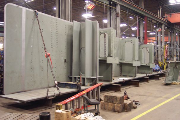
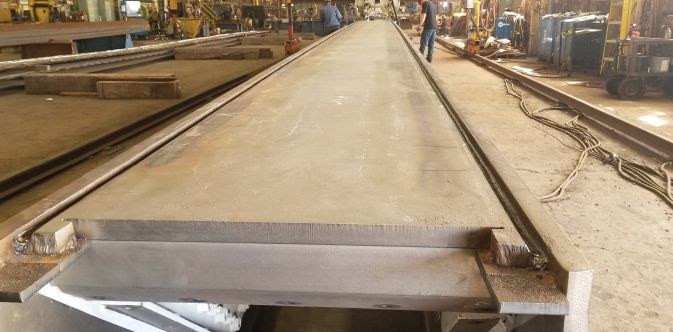
High Steel Structures, LLC (High Steel) fabricated the bent cap and found it both relatively easy to fabricate and, given the ease of fabrication, cost-effective compared to traditional bent cap boxes. High Steel estimates that three-girder caps are about one half the cost of traditional boxes. Computer numerically controlled (CNC) drilling is the key to the economical fabrication of the three I-girder caps.
 |
|
Fig. 5. Box assembly is slow and laborious. Above, a box is being built
|
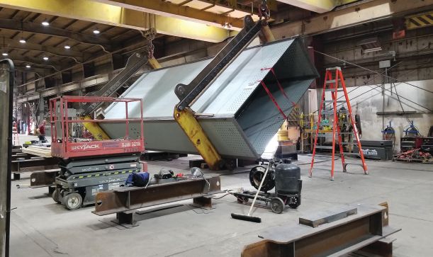
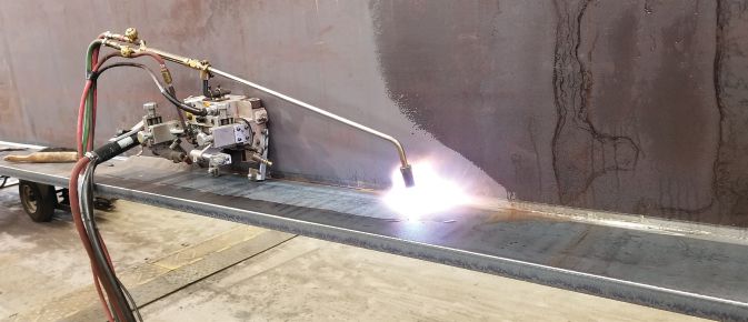
Boxes are usually painted on the inside, primarily to help facilitate in-service inspection. To help reduce work inside the box, webs and flanges are precleaned, masked, and painted before the box is built, and then any needed touch-up painting is performed after the box is built. Other tasks are also particularly challenging to accomplish inside of boxes, especially welding, which requires dragging welding guns and leads through boxes and heightened ventilation to removed welding fumes. Complicating the traditional box building process, box web-to-flange corners often have complete joint penetration (CJP) welds, whereas I-girder webs and flanges are joined with fillet welds. The CJP welds require more steps to make, as compared in Table 1. The greatest savings in the three I-girder caps are in the fabrication operations. With traditional boxes, it takes considerable effort to join all four sides so that the webs and flanges are properly fit to each other and to the internal diaphragms and other internal elements. As shown in Figure 5, fabricators typically assemble one web to one flange, add the diaphragms, add the second web, and then finally add the second flange to close the box, adjusting elements using heat along the way to help achieve fit. These steps take considerable time and effort. By contrast, the three I-girder webs and flanges are joined using typical I-girder fabrication, which is much simpler.
| Step | Web-to-Flange CJP Corner Weld | Web-to-Flange Fillet Weld |
|---|---|---|
| Bevel web | Needed | Not Needed |
| Fabricate continuous backing and attach to web | Needed | Not Needed |
| Fit web to flange | Needed | Needed |
| Weld | Ten to fifteen passes (assuming a 1-in.-thick web) | Two passes done simultaneously, one each on either side of web (assuming a 5/16-in. fillet weld) |
| Perform ultrasonic testing | Needed | Not needed |
| Perform magnetic particle testing | Not needed | Needed |
Table 1. A comparison of web-to-flange CJP welds to web-to-flange fillet welds.
Note that the CJP welds require many more passes to make than the fillet welds, are usually single-pass, and are done simultaneously, saving time.
Figure 7 shows an exploded view of the three-girder cap. The exploded assembly looks more complicated than a box, but from a fabrication standpoint it is much less so because of what it takes to fit the parts. As described above, fitting welded diaphragms in boxes is painstaking and complicated. In the three-girder cap, fitting is accomplished by pinning diaphragms and girders to align the connections and then bolting them. The key, then, is accurately making the holes such that holes line up readily.
 |
|
Fig. 6. Traditional box web-to-flange CJPs require backing, bevels, and multiple passes (above),
|
|
Fig. 7. A model view of a diaphragm-to-girder assembly. |
An older method of making holes is to assemble the parts to be joined and then drill the holes with the parts together, either drilling one time through blank steel in both parts or starting with sub-size holes in the individual parts and then reaming the holes to final size with the parts together. These methods are still useful in fabrication, but today’s CNC equipment is much more productive for many applications, and it is CNC processing that makes the three-girder cap economical. Using CNC equipment like the plate processor, the three-girder cap connections were made with this workflow:
- Cutting and drilling programs were produced for the connection plates and for the diaphragms. The same bolt hole pattern information was used in the connection plates and associated diaphragms to help ensure the parts will fit.
- Connection plates were installed in the girders in the shop during girder building.
- Later, in the yard, the girders were supported in the no-load condition next to each other.
- Diaphragms were brought to the girders, and pins were used to align the connection.
- Some bolts were used to hold the girders together.
- Bolts holes throughout the connections were checked for proper alignment
|
Fig. 8. A CNC plate processor (left) was used to make the
|
As shown in Figure 8, the diaphragms fit neatly and accurately between the girders.
Some fine adjustments of the girders were needed to build the cap. AASHTO/AWS D1.5 provides girder camber and sweep tolerances (represented at left in Figure 9), but these tolerances are intended for traditional bridge construction. Bridges have much wider spacing are more tolerant of girder camber and sweep variations than the three-girder cap. Pinning the diaphragms is effective for pulling the girders together into the correct and needed final orientation, but first, the girders must be relatively close, and tighter tolerances are needed. As indicated by the markings on the girder flange shown in the right image of Figure 9, High Steel made some girder sweep corrections to get everything to fit. Generally, it is normal for fabricators to make such fine adjustments needed to get things to fit, but because D1.5 tolerances are not sufficient for this assembly, it is recommended to include a note in the plans indicating that the tighter-than-normal camber and sweep tolerances are probably necessary for these girders. Further, if the girders are to be shipped separately and assembled in the field, then it is prudent to check the fit of assembly at the shop.
In addition to the cost and time savings associated with the three-girder cap, there is also a safety advantage in its fabrication. Boxes are confined spaces and thereby pose a safety risk. Fabricators effectively manage this risk by being prepared for the eventuality that a coworker has a health emergency while inside the box, but it is preferable to avoid the risk entirely.
|
Fig. 9. A representation of girder camber and sweep tolerances, shown at left;
|
From the standpoint of fabrication, the three-girder cap is relatively easy to fabricate and much more cost-effective than a traditional welded box bent cap. This reality depends on the use of CNC processing to make connection plates and diaphragm such that they will fit without drilling or reaming in assembly. Subdrill and ream processing is not inherently bad, but this process would be difficult and costly to execute within the assembled cap. Tighter-than-normal tolerances are needed for the girders; just how much depends on the girder spacing and the girder connection plate spacing. Regardless, proficient bridge fabricators will recognize this need as they make plans to build these boxes.
|
Fig. 10. Erection of the cap. |
The construction of the bridge has progressed smoothly. Two of the three girders were shipped assembled, and the third girder was shipped separately and then attached in the field. The entire straddle cap assembly was erected in one piece during a short overnight road closure, as shown in Figure 10. The erection of the superstructure trapezoidal girders followed shortly after that.
|
Fig. 11. Completed erection of the framing. |
At this time, the entire superstructure erection is complete, as shown in Figure 11. The use of the triple I-Girder straddle cap has proven to be a successful design. The design is cost-effective, provides load path redundancy, and facilitates the shipping and erection process. This concept is flexible and can be applied to all typical straddle bent designs, including integral bents. Elimination of a fracture-critical designation will save the owner costs over the long-term due to the elimination of fracture critical member inspections.
Owner
Connecticut Department of Transportation
General Contractor
O&G Industries/Barletta Heavy Division, Joint Venture
Structural Engineer
CHA Consulting
Steel Team
Fabricator
High Steel Structures, LLC , Lancaster, Pa.
Erector
Hartland Building and Restoration Co. , East Granby, Conn.
Detailer
ABS Structural Corp. , Melbourne, Fla.
 Fig. 1. A plan view of Interchange 29.


